



Discussed in this article : Pre-Installation Steps, Installation Instructions for Wall Mounted Exit Signs, Installation Instructions for Ceiling or Side Mounted Exit Signs
Pre-Installation Steps:
- Consider the mounting configuration. A Flush Mount / Wall Mount uses the knockouts on the backside of unit to attach directly to a junction box or to drywall/concrete using wall anchors. Most Exit Signs include a mounting canopy which attaches to the side or the top of the unit and mates to a junction box or drywall/concrete as well. Combination exits with emergency lights located on the side, typically only allow flush or top mount since the heads are attached on the sides and leave no room for the mounting canopy. For a better understanding, visit our Exit Sign Mounting Configurations Explained article.
- Consider the voltage you will be using. Most standard units allow for 120 OR 277 VAC operation and will have the appropriate wires labeled. Determine the input voltage on the circuit you are installing on and plan to use the corresponding wires accordingly.
- Turn off the circuit. Never attempt to install an exit sign on a live circuit. Rather, turn off the power at the panel and follow lockout/tagout procedure.
Exit sign mounting configurations
When deciding what type of exit sign or emergency light to purchase, mounting configuration matters. These illustrations clarify common configurations and help you choose the option that fits your installation.
Flush mount / wall mount
Does not use a mounting canopy. Back-plate knockouts typically attach directly to a junction box. Some emergency-light fixtures also allow ceiling mounting this way.
Ceiling mount
Typically uses a canopy attached to the top of the fixture. Check whether the unit is specified for drop-ceiling/new-construction or sheet-rock/remodel work. Exit signs may require a double face.
Side mount
Often confused with a flush wall mount, side mounting uses a canopy on the side of the unit, then attaches it to the wall. Exit signs may require a double face.
Wall mount, angle down
Mostly used with edge-lit signs. A canopy attaches above the unit; the sign face angles down. Recessed versions may use a curved face.
Recessed mount
The sign housing sits above the ceiling while the face remains visible below it. Confirm whether the product is designed for drop-ceiling/new-construction or sheet-rock/remodel installation.
Pendant mount
Uses a pendant kit, sometimes an optional accessory, to suspend a ceiling-mountable unit where a high or sloped ceiling makes it easier to see.
Wall Mounted Exit Sign Installation Steps:
- Remove the front faceplate
- Knock out mounting holes from the back faceplate to match the junction box configuration
- Feed the input wires through the back faceplate
- If the exit sign housing is metal, wire and cap the green ground wire to the corresponding ground wire in junction box (plastic housing exits will have no ground wire)
- Place the white common (neutral) wires together and cap them with a wire nut (included)
- Wire and cap either the 120V (black) or 277V (red/orange) wire with the line input wire (depending on the decided voltage)
- Cap off the remaining wire that was not used
- Fasten the back faceplate to the junction box with the included screws leaving all installation wiring inside the junction box
- Connect the battery to the circuit board
- Reattach the front faceplate
Ceiling Mounted / Side Mounted Exit Sign Installation Steps:
- Remove the front faceplate
- Pop out the mounting canopy knockouts on either the top or the side of unit
- Attach the mounting canopy
- Attach the metal grid to the mounting canopy with included screws using the configuration of the junction box
- Feed the input wires through the mounting canopy
- If the exit sign housing is metal, wire and cap the green ground wire to the corresponding ground wire in junction box (plastic housing exits will have no ground wire)
- Place the white common (neutral) wires together and cap them with a wire nut (included)
- Wire and cap either the 120V (black) or 277V (red/orange) wire with the line input wire (depending on the decided voltage)
- Cap off the remaining wire that was not used
- Fasten the mounting canopy to the junction box with the included screws leaving all installation wiring inside the junction box
- Connect the battery to the circuit board
- Reattach the front faceplate
Haven't purchased an Exit Sign Yet? Shop our Exit Lights

Edge Lit Red LED Exit Sign | Surface or Recessed Mount
Edge-lit LED exit sign with surface or recessed mounting options.
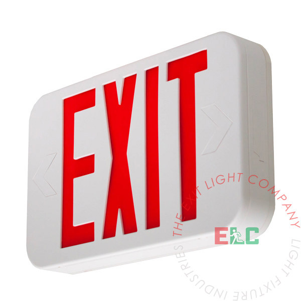
Modern Design Red LED Exit Sign | White Housing
Modern red LED exit sign in a white housing.
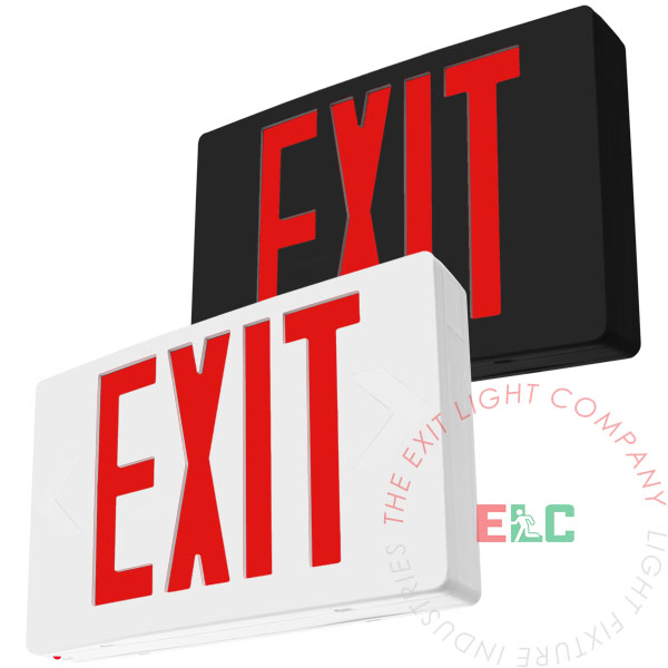
Standard Red LED Exit Sign | White or Black Housing
Standard red LED exit sign with white or black housing options.